Monday 28 September 2009

Rework and headaches


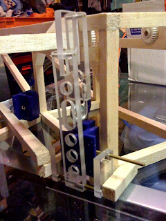
I've reworked the nacelle steerer setup because I wasn't happy with the gears, and it wasn't working as I'd planned. The servos used here are old cheapo ones but one is modifed to work in reverse. I can't remember how I did this (I'll post it when I remember) but it was convenient as the same signal can applied to both servos to make the nacelles turn the same way.

The first front leg is fixed in place and a rear one is getting there. I abandoned the vertical offset angle just for simplicity, as I'd like to move on to the flight systems.

Next: finish L/G and start on tail.

Thursday 24 September 2009

Micro servos arrive!

How small are these? I got 8 micro servos from eBay for use on the light-weight jobs (steering vanes, pan & tilt etc). The servo on the left is a "standard" size and the new "9g" servo on the right, which is smaller than I imagined.


What does it all mean!

I've been asked what some of the acronyms and abreviations mean. I assumed the reader would have a similar level of knowledge, but this is not the case, and I appologise. In the side bar >>> you'll find a list, which will hopefully make things a little clearer.
I haven't yet got to the stage of talking about the FPV system with OSD while the AP and IMU does it's thing with the EDFs via the ESCs ;-)
I'll add more as and when they come up, or are requested.

Sunday 20 September 2009

L/G - doing things the hard way

Because I want a cargo ramp on the bottom, to allow for a small rover, the ground clearance has to be quite high. I also want the L/G to be sprung to absorb the impact of touchdown, and they'll have to fit at in a tight spot at an odd angle (both vertically and horizontally).

I've spent hours trying to figure out how I want these to mount.


I used the drawing (see previous post) as a template for the parts.

The mock-up of the mech works as expected (shown below, without the "leg" part attached).


They'll be painted eventually.


I had to make a small mod to stop the coil spring clashing with the lower arm.


I think I'll have to make it a bit shorter too.

Landing gear design

I've been working on the design for the landing gear. I had a specific style in mind and it will have to provide enough ground clearance for the payload ramp, some sprung shock absorbtion and work with the odd body angles in the planned loaction. I'll make some parts to check that the concept works and won't conflict with anything before making all of them. I also need to check for conflicts with the nacelle steerer servos.

Friday 18 September 2009

Nacelle shaft drives

It's a bit tight in there, but the servo drives are coming along. The gears are from an old printer. I'm not entirely happy with this setup though. Can't put my finger on why...


Saturday 12 September 2009

First nacelle

It took me a while to figure out how I was going to do the steerable arms for the two front EDFs. What I came up with seems pretty strong, and will allow a servo to adjust the angle from inside the main body. I only want the end section with the EDF to rotate, not the whole arm. Distance between centres of each EDF is 500mm.

Friday 11 September 2009

Work starts on airframe

I started out using wood glue, but it took forever to go off. So I switched to hot-melt and that seems to work a treat.
Still plenty to do, and even with the EDF held in place with just a couple of small bulldog clips, I couldn't resist powering it up... makes me grin everytime!

Thursday 3 September 2009

Balanced rotors

I tried balancing the rotors with slivers of electrical tape (as I'd seen done on YouTube) but they appeared to be more out-of-balance than I thought. I ended up balancing the rotors with "Blu-Tack", adding a little each time.
Sorry about the poor image quality (damn iPhone).

I mounted the balanced rotors back in their housings and powered up for another test. This time I had a current meter set up to measure total current. Although the balancing still isn't perfect it is a huge improvement, with much less vibration evident. I ramped up the power and the rig started to get light. The current clamp showed ~20A. By ~30A the rig was "hovering". Amid the noise, wind and threat of exploding plastic; I dared to wind up the power some more and at ~64A the rig was actively trying to reach the ceiling. That was just before one of the rotors whizzed passed my head! I'd secured the rotors to the "shaft", but neglected to check if the rotor adapters were tight on the motor shaft. Luckily, no damage done. I'm sure I've barely reached half "throttle".
Next job: tighten shaft adapters and start on stiffer airframe.

Wednesday 2 September 2009

Test rig - quick and dirty

This is the rig I threw together to get a feel for the how the as yet un-balanced EDFs would perform (I couldn't wait). The sealed lead acid battery is in parallel with the PSU to help iron out the sags.
The rig showed me how powerful these are, and how important it will be to get the balancing right. I did manage to power up all three but had to back off due to some serious vibration. I think the frame didn't help as the lack of rigidity allowed any vibration to resonate.
Must balance rotors!